
I love to use soft gradients as backdrops when doing graphics programming, a love started by a Corona Renderer product shot sample scene shared by user romullus and its use of radial gradients to highlight the product. But they are quite horrible from a design standpoint, since they produce color banding, also called posterization.
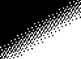
Depending on things like screen type, gradient colors, viewing environment, etc., the effect can be sometimes not present at all, yet sometimes painfully obvious. Let’s take a look at what I mean. The following is a WebGL Canvas drawing a black & white, dark and soft half-circle gradient.
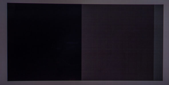
Screenshot, in case WebGL doesn't work
WebGL Vertex Shader fullscreen-tri.vs
attribute vec2 vtx;
varying vec2 tex;
void main()
{
	tex = vtx;
	gl_Position = vec4(vtx, 0.0, 1.0);
}
WebGL Fragment Shader banding.fs
precision mediump float;
varying vec2 tex;

void main(void)
{
	vec3 outsidecolor = vec3(0.15);
	vec3 insidecolor = vec3(0.2);
	vec3 bgcolor = mix(insidecolor, outsidecolor,
					   length(vec2(tex.x, tex.y * 0.5 + 1.0)));
	gl_FragColor = vec4(bgcolor, 1.0);
}
WebGL Javascript fullscreen-tri.js
"use strict";
function setupTri(canvasId, vertexId, fragmentId) {
	/* Init */
	const canvas = document.getElementById(canvasId);
	const gl = canvas.getContext('webgl', { preserveDrawingBuffer: false });

	/* Shaders */
	const vertexShader = createAndCompileShader(gl.VERTEX_SHADER, vertexId);
	const fragmentShader = createAndCompileShader(gl.FRAGMENT_SHADER, fragmentId);

	const shaderProgram = gl.createProgram();
	gl.attachShader(shaderProgram, vertexShader);
	gl.attachShader(shaderProgram, fragmentShader);
	gl.linkProgram(shaderProgram);
	gl.useProgram(shaderProgram);

	/* Vertex Buffer with a Fullscreen Triangle */
	const unitTri = new Float32Array([
		-1.0, 3.0,
		-1.0, -1.0,
		3.0, -1.0
	]);

	const vertex_buffer = gl.createBuffer();
	gl.bindBuffer(gl.ARRAY_BUFFER, vertex_buffer);
	gl.bufferData(gl.ARRAY_BUFFER, new Float32Array(unitTri), gl.STATIC_DRAW);

	const vtx = gl.getAttribLocation(shaderProgram, "vtx");
	gl.enableVertexAttribArray(vtx);
	gl.vertexAttribPointer(vtx, 2, gl.FLOAT, false, 0, 0);

	function redraw() {
		gl.viewport(0, 0, canvas.width, canvas.height);
		gl.drawArrays(gl.TRIANGLES, 0, 3);
	}

	function createAndCompileShader(type, source) {
		const shader = gl.createShader(type);
		gl.shaderSource(shader, document.getElementById(source).text);
		gl.compileShader(shader);
		if (!gl.getShaderParameter(shader, gl.COMPILE_STATUS)) {
			console.error(gl.getShaderInfoLog(shader));
		}
		return shader;
	}

	/* 1:1 Pixel Mapping */
	/* Awesome solution by https://stackoverflow.com/a/35244519/6240779 */
	function onResize() {
		const dipRect = canvas.getBoundingClientRect();
		const width = Math.round(devicePixelRatio * dipRect.right)
			- Math.round(devicePixelRatio * dipRect.left);
		const height = Math.round(devicePixelRatio * dipRect.bottom)
			- Math.round(devicePixelRatio * dipRect.top);

		if (canvas.width !== width || canvas.height !== height) {
			canvas.width = width;
			canvas.height = height;
			redraw();
		}
	}
	window.addEventListener('resize', onResize, true);
	onResize();
};

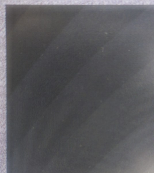
This produces a 24-bit (8-bits per channel) image with clearly visible banding steps. If you don’t see the banding due to being in a bright environment or having the screen brightness set to very low, reference the pictures below. Here is what it should look like on an 8-bit panel, specifically the HP Z24n G2 monitor.
It should also look the same on a high-end 10-bit or 12-bit panel, since WebGL doesn’t allow high bit-depth output. The image is brightness and contrast boosted, to make the steps obvious.
Many Laptop screens are in fact 6-bit panels performing dithering to fake an 8-bit output. This includes even high-priced workstation replacements, like the HP Zbook Fury 15 G7 and its 6-bit LCD panel, that I sit in front of right now. Here is a photo of the above WebGL sample on that 6-bit panel.
Panel's built-in dithering visualized.
It's not obvious from the photo, but the dither pattern is distinctly visible when looking closely with the naked eye.

What you can see are some banding steps being a clean uniform color and some of them being dithered via the panel’s integrated look-up table to achieve a perceived 8-bit output via ordered dithering. Though note, how the dithering does not result in the banding steps being broken up, it just dithers the color step itself.
Capturing this via a photo is a bit difficult, since there is also the pattern of individual pixels messing with the capture and introducing moiré and interference patterns.
Magic GLSL One-liner #
Let’s fix this. The main point of this article is to share how I get banding free gradients in one GLSL fragment shader, rendering in a single pass and without sampling or texture taps to achieve banding free-ness. It involves the best noise one-liner I have ever seen. That genius one-liner is not from me, but from Jorge Jimenez in his presentation on how Gradient noise was implemented in Call of Duty: Advanced Warfare. You can read it on the presentation’s slide 123 onwards. It’s described as:
[…] a noise function that we could classify as being half way between dithered and random, and that we called Interleaved Gradient Noise.
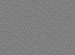
Here is what the raw noise looks like. The following WebGL Canvas is set to render at the same pixel density as your screen.
Screenshot, in case WebGL doesn't work
WebGL Vertex Shader noise.vs
attribute vec2 vtx;
void main()
{
	gl_Position = vec4(vtx, 0.0, 1.0);
}
WebGL Fragment Shader noise.fs
precision highp float;

/* Gradient noise from Jorge Jimenez's presentation: */
/* http://www.iryoku.com/next-generation-post-processing-in-call-of-duty-advanced-warfare */
float gradientNoise(in vec2 uv)
{
	return fract(52.9829189 * fract(dot(uv, vec2(0.06711056, 0.00583715))));
}

void main(void)
{
	gl_FragColor = vec4(vec3(0.0) + gradientNoise(gl_FragCoord.xy), 1.0);
}
WebGL Javascript fullscreen-tri.js
"use strict";
function setupTri(canvasId, vertexId, fragmentId) {
	/* Init */
	const canvas = document.getElementById(canvasId);
	const gl = canvas.getContext('webgl', { preserveDrawingBuffer: false });

	/* Shaders */
	const vertexShader = createAndCompileShader(gl.VERTEX_SHADER, vertexId);
	const fragmentShader = createAndCompileShader(gl.FRAGMENT_SHADER, fragmentId);

	const shaderProgram = gl.createProgram();
	gl.attachShader(shaderProgram, vertexShader);
	gl.attachShader(shaderProgram, fragmentShader);
	gl.linkProgram(shaderProgram);
	gl.useProgram(shaderProgram);

	/* Vertex Buffer with a Fullscreen Triangle */
	const unitTri = new Float32Array([
		-1.0, 3.0,
		-1.0, -1.0,
		3.0, -1.0
	]);

	const vertex_buffer = gl.createBuffer();
	gl.bindBuffer(gl.ARRAY_BUFFER, vertex_buffer);
	gl.bufferData(gl.ARRAY_BUFFER, new Float32Array(unitTri), gl.STATIC_DRAW);

	const vtx = gl.getAttribLocation(shaderProgram, "vtx");
	gl.enableVertexAttribArray(vtx);
	gl.vertexAttribPointer(vtx, 2, gl.FLOAT, false, 0, 0);

	function redraw() {
		gl.viewport(0, 0, canvas.width, canvas.height);
		gl.drawArrays(gl.TRIANGLES, 0, 3);
	}

	function createAndCompileShader(type, source) {
		const shader = gl.createShader(type);
		gl.shaderSource(shader, document.getElementById(source).text);
		gl.compileShader(shader);
		if (!gl.getShaderParameter(shader, gl.COMPILE_STATUS)) {
			console.error(gl.getShaderInfoLog(shader));
		}
		return shader;
	}

	/* 1:1 Pixel Mapping */
	/* Awesome solution by https://stackoverflow.com/a/35244519/6240779 */
	function onResize() {
		const dipRect = canvas.getBoundingClientRect();
		const width = Math.round(devicePixelRatio * dipRect.right)
			- Math.round(devicePixelRatio * dipRect.left);
		const height = Math.round(devicePixelRatio * dipRect.bottom)
			- Math.round(devicePixelRatio * dipRect.top);

		if (canvas.width !== width || canvas.height !== height) {
			canvas.width = width;
			canvas.height = height;
			redraw();
		}
	}
	window.addEventListener('resize', onResize, true);
	onResize();
};
Now let’s combine both previous WebGL examples to clear the color banding and get a smooth half-circle gradient.
Screenshot, in case WebGL doesn't work
You have to view this at 1:1 pixel scale, otherwise your browser’s will counteract the pixel sized dither and re-introduce color banding!
WebGL Vertex Shader fullscreen-tri.vs
attribute vec2 vtx;
varying vec2 tex;
void main()
{
	tex = vtx;
	gl_Position = vec4(vtx, 0.0, 1.0);
}
WebGL Fragment Shader gradient.fs
precision highp float;
varying vec2 tex;

/* Gradient noise from Jorge Jimenez's presentation: */
/* http://www.iryoku.com/next-generation-post-processing-in-call-of-duty-advanced-warfare */
float gradientNoise(in vec2 uv)
{
	return fract(52.9829189 * fract(dot(uv, vec2(0.06711056, 0.00583715))));
}

void main(void)
{
	vec3 outsidecolor = vec3(0.15);
	vec3 insidecolor = vec3(0.2);
	vec3 bgcolor = mix(insidecolor, outsidecolor,
					   length(vec2(tex.x, tex.y * 0.5 + 1.0)));
	bgcolor += (1.0 / 255.0) * gradientNoise(gl_FragCoord.xy) - (0.5 / 255.0);

	gl_FragColor = vec4(bgcolor, 1.0);
}
WebGL Javascript fullscreen-tri.js
"use strict";
function setupTri(canvasId, vertexId, fragmentId) {
	/* Init */
	const canvas = document.getElementById(canvasId);
	const gl = canvas.getContext('webgl', { preserveDrawingBuffer: false });

	/* Shaders */
	const vertexShader = createAndCompileShader(gl.VERTEX_SHADER, vertexId);
	const fragmentShader = createAndCompileShader(gl.FRAGMENT_SHADER, fragmentId);

	const shaderProgram = gl.createProgram();
	gl.attachShader(shaderProgram, vertexShader);
	gl.attachShader(shaderProgram, fragmentShader);
	gl.linkProgram(shaderProgram);
	gl.useProgram(shaderProgram);

	/* Vertex Buffer with a Fullscreen Triangle */
	const unitTri = new Float32Array([
		-1.0, 3.0,
		-1.0, -1.0,
		3.0, -1.0
	]);

	const vertex_buffer = gl.createBuffer();
	gl.bindBuffer(gl.ARRAY_BUFFER, vertex_buffer);
	gl.bufferData(gl.ARRAY_BUFFER, new Float32Array(unitTri), gl.STATIC_DRAW);

	const vtx = gl.getAttribLocation(shaderProgram, "vtx");
	gl.enableVertexAttribArray(vtx);
	gl.vertexAttribPointer(vtx, 2, gl.FLOAT, false, 0, 0);

	function redraw() {
		gl.viewport(0, 0, canvas.width, canvas.height);
		gl.drawArrays(gl.TRIANGLES, 0, 3);
	}

	function createAndCompileShader(type, source) {
		const shader = gl.createShader(type);
		gl.shaderSource(shader, document.getElementById(source).text);
		gl.compileShader(shader);
		if (!gl.getShaderParameter(shader, gl.COMPILE_STATUS)) {
			console.error(gl.getShaderInfoLog(shader));
		}
		return shader;
	}

	/* 1:1 Pixel Mapping */
	/* Awesome solution by https://stackoverflow.com/a/35244519/6240779 */
	function onResize() {
		const dipRect = canvas.getBoundingClientRect();
		const width = Math.round(devicePixelRatio * dipRect.right)
			- Math.round(devicePixelRatio * dipRect.left);
		const height = Math.round(devicePixelRatio * dipRect.bottom)
			- Math.round(devicePixelRatio * dipRect.top);

		if (canvas.width !== width || canvas.height !== height) {
			canvas.width = width;
			canvas.height = height;
			redraw();
		}
	}
	window.addEventListener('resize', onResize, true);
	onResize();
};

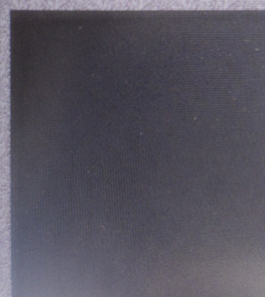
Perfectly smooth on my monitor with the 8-bit panel!

Same monitor and photo setup as the color-banded mess from the beginning of the article. No trickery with different zoom levels or filters. The noise is essentially invisible. It’s my own article and still I’m surprised myself at the effectiveness of that simple one-liner.
The proper way to achieve banding free-ness is error diffusion dithering. It breaks up just the quantized steps of the gradient, without touching the color in-between. But other than ordered dithering, there is no GPU friendly way to do this and even very faint ordered dithering with its fixed pattern is easily detected by human vision.
When talking about gradients, adding noise works just fine though, even though it’s not proper error diffusion. Simply applying noise with the strength of one 8-bit grayscale value (1.0 / 255.0) * gradientNoise(gl_FragCoord.xy) side-steps a bunch of issues and the code footprint is tiny to boot.
Additionally we subtract the average added brightness of (0.5 / 255.0) to keep the brightness the same, since we are introducing the noise via addition, though the difference is barely noticeable. Here is a part of the gradient with a threshold applied and zoomed in, to see how both gradient and noise interact.
Here is how I usually use this Shader setup to draw a background for objects and scenes to live on.
Screenshot, in case WebGL doesn't work
You have to view this at 1:1 pixel scale, otherwise your browser’s will counteract the pixel sized dither and re-introduce color banding!
WebGL Vertex Shader fullscreen-tri.vs
attribute vec2 vtx;
varying vec2 tex;
void main()
{
	tex = vtx;
	gl_Position = vec4(vtx, 0.0, 1.0);
}
WebGL Fragment Shader full_example.fs
precision highp float;
varying vec2 tex;

/* Gradient noise from Jorge Jimenez's presentation: */
/* http://www.iryoku.com/next-generation-post-processing-in-call-of-duty-advanced-warfare */
float gradientNoise(in vec2 uv)
{
	return fract(52.9829189 * fract(dot(uv, vec2(0.06711056, 0.00583715))));
}

void main(void)
{
	vec3 outsidecolor = vec3(0.22, 0.23, 0.25);
	vec3 insidecolor = vec3(0.40, 0.41, 0.45);
	vec3 bgcolor = mix(insidecolor, outsidecolor,
					   length(tex));
	bgcolor += (1.0 / 255.0) * gradientNoise(gl_FragCoord.xy) - (0.5 / 255.0);

	gl_FragColor = vec4(bgcolor, 1.0);
}
WebGL Javascript fullscreen-tri.js
"use strict";
function setupTri(canvasId, vertexId, fragmentId) {
	/* Init */
	const canvas = document.getElementById(canvasId);
	const gl = canvas.getContext('webgl', { preserveDrawingBuffer: false });

	/* Shaders */
	const vertexShader = createAndCompileShader(gl.VERTEX_SHADER, vertexId);
	const fragmentShader = createAndCompileShader(gl.FRAGMENT_SHADER, fragmentId);

	const shaderProgram = gl.createProgram();
	gl.attachShader(shaderProgram, vertexShader);
	gl.attachShader(shaderProgram, fragmentShader);
	gl.linkProgram(shaderProgram);
	gl.useProgram(shaderProgram);

	/* Vertex Buffer with a Fullscreen Triangle */
	const unitTri = new Float32Array([
		-1.0, 3.0,
		-1.0, -1.0,
		3.0, -1.0
	]);

	const vertex_buffer = gl.createBuffer();
	gl.bindBuffer(gl.ARRAY_BUFFER, vertex_buffer);
	gl.bufferData(gl.ARRAY_BUFFER, new Float32Array(unitTri), gl.STATIC_DRAW);

	const vtx = gl.getAttribLocation(shaderProgram, "vtx");
	gl.enableVertexAttribArray(vtx);
	gl.vertexAttribPointer(vtx, 2, gl.FLOAT, false, 0, 0);

	function redraw() {
		gl.viewport(0, 0, canvas.width, canvas.height);
		gl.drawArrays(gl.TRIANGLES, 0, 3);
	}

	function createAndCompileShader(type, source) {
		const shader = gl.createShader(type);
		gl.shaderSource(shader, document.getElementById(source).text);
		gl.compileShader(shader);
		if (!gl.getShaderParameter(shader, gl.COMPILE_STATUS)) {
			console.error(gl.getShaderInfoLog(shader));
		}
		return shader;
	}

	/* 1:1 Pixel Mapping */
	/* Awesome solution by https://stackoverflow.com/a/35244519/6240779 */
	function onResize() {
		const dipRect = canvas.getBoundingClientRect();
		const width = Math.round(devicePixelRatio * dipRect.right)
			- Math.round(devicePixelRatio * dipRect.left);
		const height = Math.round(devicePixelRatio * dipRect.bottom)
			- Math.round(devicePixelRatio * dipRect.top);

		if (canvas.width !== width || canvas.height !== height) {
			canvas.width = width;
			canvas.height = height;
			redraw();
		}
	}
	window.addEventListener('resize', onResize, true);
	onResize();
};

Don’t Double Dither #
But what about that 6-bit laptop screen? Let’s take a look, by photographing the dithered gradient like in the beginning of the article…
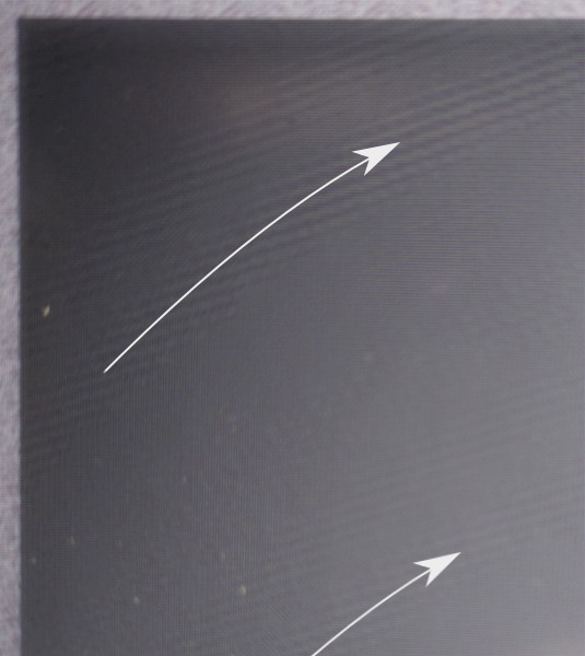
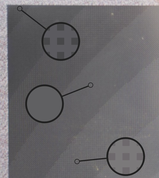
Arrows to show the interference following the gradient direction
...ohh you gotta be kidding me

Both the 6-bit screen’s dithering pattern and our Interleaved Gradient Noise interfere with each other. Exactly the color bands where the panel performs the dithering, we can see the interference appearing in the form of saw-tooth ridges.
Maybe by increasing the noise strength to correspond to 6-bit values? (1.0 / 63.0) * gradientNoise(gl_FragCoord.xy) - (0.5 / 63.0) By dividing by 63 (2⁶-1) instead of 255, we get 6-bit noise. Let’s see…
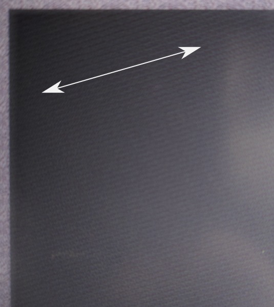
Arrows to show the interference direction
...it's worse!

Clearly obvious diagonal stripes throughout the whole gradient. Yeah, 6-bit panels are a travesty. Especially on a product of this caliber. I mean the old Thinkpad T500 & X200 I hardware modded have 6-bit panels, but those are multiple tech generations old. We could tweak the noise algorithm, but dropping to such a low common denominator is just not worth it.
It's 2024 in a couple days and every human being deserves at least 256 different shades in each color channel.

Bufferless Version #
Here is what the shaders look like if you use OpenGL 3.3+, OpenGL 2.1 with the GL_EXT_gpu_shader4 extension (#version would have to change) or WebGL2 and want to skip the Vertex Buffer setup by putting the fullscreen triangle into the vertex shader. If you get an error around gl_VertexID missing, you don’t have GL_EXT_gpu_shader4 enabled.
These can be rewritten to work with even the most basic OpenGL or WebGL standard by uploading the vertex buffer prior, as done in all the WebGL examples up till now. The fragment shader stays basically the same.
Bufferless Vertex Shader
#version 330
out vec2 tex;

const vec2 pos[3] = vec2[] (
    vec2(-1.0, -1.0),
    vec2( 3.0, -1.0),
    vec2(-1.0,  3.0)
);

void main()
{
    tex = pos[gl_VertexID];
    gl_Position = vec4(pos[gl_VertexID], 0.0, 1.0);
}
Bufferless Fragment Shader
#version 330
in vec2 tex;
out vec4 Out_Color;

/* Gradient noise from Jorge Jimenez's presentation: */
/* http://www.iryoku.com/next-generation-post-processing-in-call-of-duty-advanced-warfare */
float gradientNoise(in vec2 uv)
{
    return fract(52.9829189 * fract(dot(uv, vec2(0.06711056, 0.00583715))));
}

vec3 outsidecolor = vec3(0.22, 0.23, 0.25);
vec3 insidecolor = vec3(0.40, 0.41, 0.45);

void main()
{
    vec3 bgcolor = mix(insidecolor, outsidecolor,
                       sqrt(tex.x * tex.x + tex.y * tex.y));

    /* Add gradient noise to reduce banding. */
    bgcolor += (1.0 / 255.0) * gradientNoise(gl_FragCoord.xy) - (0.5 / 255.0);
    Out_Color = vec4(bgcolor, 1.0);
}
What are the big-boys doing? #
To finish off, let’s take a look how color banding is solved in other pieces of software. Not just in the context of gradients, but also beyond.
Valve Software #
Alex Vlachos, formerly at Valve, gave a GDC talk in 2015, where he showed off an algorithm “used for years since Portal 2 on the Xbox 360”, that Valve Software used in their “The Lab” VR demos to combat color banding.
Source: Excerpt from "Advanced VR Rendering", GDC 2015 talk by Alex Vlachos
Here is the code that was showcased in the talk, in case you want to use it yourself. Valve animates the dither, as indicated by variable g_flTime.
float3 ScreenSpaceDither( float2 vScreenPos )
{
	// Iestyn's RGB dither (7 asm instructions) from Portal 2 X360, slightly modified for VR
	float3 vDither = dot( float2( 171.0, 231.0 ), vScreenPos.xy + g_flTime ).xxx;
	vDither.rgb = frac( vDither.rgb / float3( 103.0, 71.0, 97.0 ) ) - float3( 0.5, 0.5, 0.5 );
	return ( vDither.rgb / 255.0 ) * 0.375;
}
Alien: Isolation #
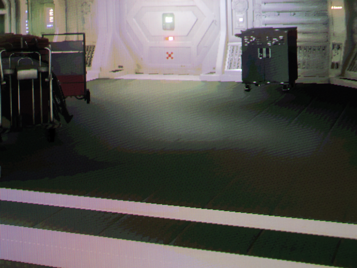
I consider Alien: Isolation to be a technical master piece in terms of lighting, especially considering the time it was released.
They faked realtime global illumination in a really interesting fashion, with the flashlight lighting up the area when shining directly at a wall fairly close and casting a redish ambiance when shining at a deep red door. It’s mostly a hardcoded fake effect working with specific surfaces, but I digress…
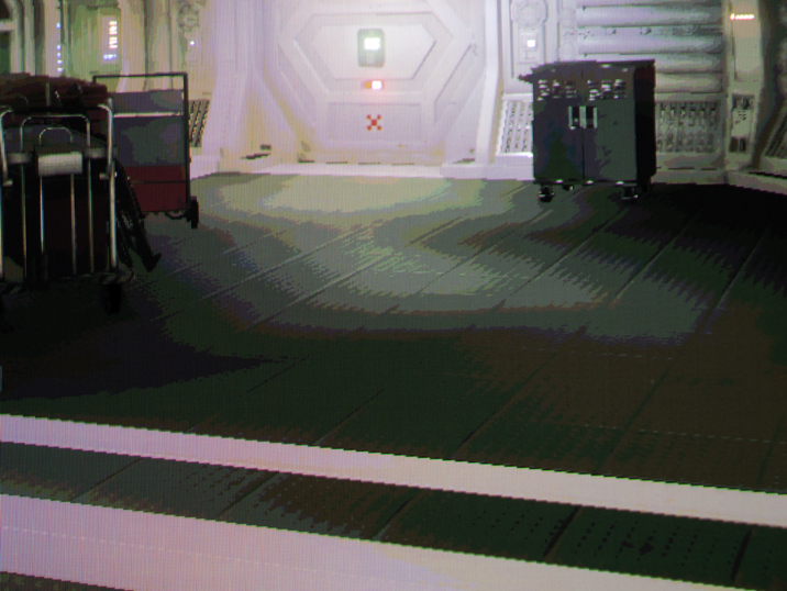
Horror games like Alien: Isolation have a lot of dark scenes with lights creating gradient like falloffs. These are very prone to color banding. The programmers over at creative assembly show multiple ways of tackling this. Let’s take a look at how by dissecting this scene.
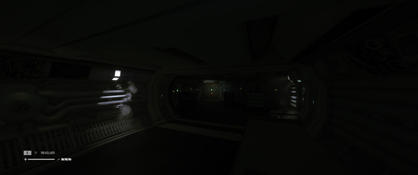
I photographed the middle of the scene, as viewed on my Alienware AW3423DW. In this first example, without any color banding mitigation and again with brightness & contrast boosted for clarity within this article. In real-life the color banding is obviously visible when gaming in a dark environment. These are actual photos and not screenshots, which will matter a little later.
Film grain #
There is of course the easy way of just slapping a lot of film grain everywhere and Alien: Isolation is definitely guilty of this. In fact way more egregious than other games, with the VHS aesthetic of huge dark blobs.
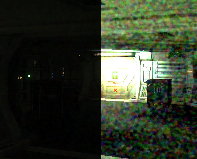
It’s not quite as bad when turned down to lower settings and during gameplay it’s animated, but I’m still not a fan. Let’s see if we can do one better…
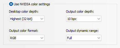
Deep-Color #

Deep Color is what outputting at 10-bits per channel is called, just like 8bpp is True Color. It’s also a setting in Alien: Isolation to enable 10bpc rendering. The way this setting works is absolutely not obvious though. You can turn it on, but it will only be actually active under a certain set of circumstances:
- Anti-Aliasing has to be disabled.
- That’s a serious bummer. None of the Anti-Aliasing shaders handle the 10-bit signal and just crush the result back down to 8-bit. It’s as if you didn’t turn it on at all :[
- Your monitor needs to accept a 10 or 12-bit signal. Otherwise, the game won’t switch into that higher bit-depth mode.
- Interestingly enough, the monitor doesn’t need to be in that mode, but that mode just has to be available and the switching happens automatically, which I did not expect. In the case of my monitor, this entails switching from 175hz to 144hz, to unlock the 10-bit color option.
- Interestingly enough, the monitor doesn’t need to be in that mode, but that mode just has to be available and the switching happens automatically, which I did not expect. In the case of my monitor, this entails switching from 175hz to 144hz, to unlock the 10-bit color option.
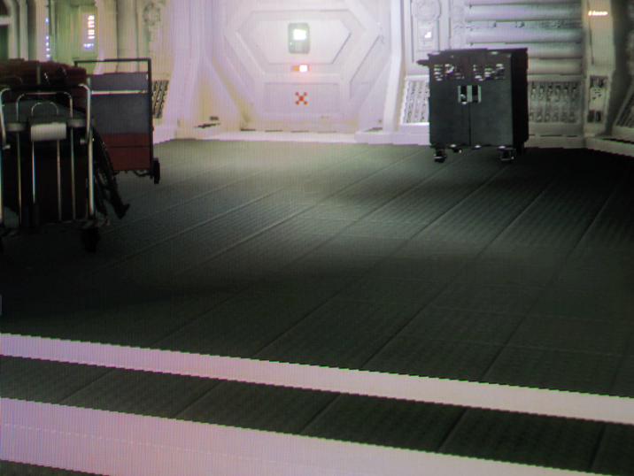
What an excellent result! All banding banished to the shadow realm.

No tricks with different processing of the photo either. The camera captured the exact same exposure and the brightness was boosted in the same way. I suspect, that it’s not just the output being 10-bit, that is giving such a good result, but also some passes being merged at a higher bit-depth and thus reducing color banding further. The result is just way too good for being a mere bump from 256 -> 1024 steps per channel. Please note, that this is in no way shape or form related to the standard of HDR. In fact, HDR is explicitly disabled in Windows.
Of course, you need to have a rather expensive screen, being able to run 10-bits per channel or higher. And even if, sometimes the graphics card you have doesn’t have the right generation of connector, leading you to have to drop color-resolution and/or refresh-rate in order to do so. What else is there?
Reshade’s Deband Effect #
ReShade (sometimes mistakenly referred to as SweetFx, a shader collection that used to be part of it) is a popular graphics hook, that applies various effects on top of many games, with many presets custom tuned by the community. ReShade’s versatility and maturity has proven itself over many years of releases and broad palette of supported games. Among the effects you can apply is “Deband” (Simply called “Dither” in the past).
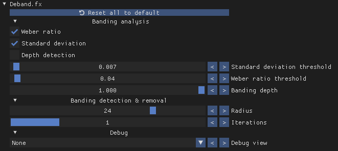
The Deband.fx Shader (Source code below, for reference) applies dithering to areas, that it detects as affected by color banding, based on the Weber Ratio.
ReShade's Deband.fx source code, for reference
/**
 * Deband shader by haasn
 * https://github.com/haasn/gentoo-conf/blob/xor/home/nand/.mpv/shaders/deband-pre.glsl
 *
 * Copyright (c) 2015 Niklas Haas
 *
 * Permission is hereby granted, free of charge, to any person obtaining a copy
 * of this software and associated documentation files (the "Software"), to deal
 * in the Software without restriction, including without limitation the rights
 * to use, copy, modify, merge, publish, distribute, sublicense, and/or sell
 * copies of the Software, and to permit persons to whom the Software is
 * furnished to do so, subject to the following conditions:
 *
 * The above copyright notice and this permission notice shall be included in
 * all copies or substantial portions of the Software.
 *
 * THE SOFTWARE IS PROVIDED "AS IS", WITHOUT WARRANTY OF ANY KIND, EXPRESS OR
 * IMPLIED, INCLUDING BUT NOT LIMITED TO THE WARRANTIES OF MERCHANTABILITY,
 * FITNESS FOR A PARTICULAR PURPOSE AND NONINFRINGEMENT. IN NO EVENT SHALL THE
 * AUTHORS OR COPYRIGHT HOLDERS BE LIABLE FOR ANY CLAIM, DAMAGES OR OTHER
 * LIABILITY, WHETHER IN AN ACTION OF CONTRACT, TORT OR OTHERWISE, ARISING FROM,
 * OUT OF OR IN CONNECTION WITH THE SOFTWARE OR THE USE OR OTHER DEALINGS IN THE
 * SOFTWARE.
 *
 * Modified and optimized for ReShade by JPulowski
 * https://reshade.me/forum/shader-presentation/768-deband
 *
 * Do not distribute without giving credit to the original author(s).
 *
 * 1.0  - Initial release
 * 1.1  - Replaced the algorithm with the one from MPV
 * 1.1a - Minor optimizations
 *      - Removed unnecessary lines and replaced them with ReShadeFX intrinsic counterparts
 * 2.0  - Replaced "grain" with CeeJay.dk's ordered dithering algorithm and enabled it by default
 *      - The configuration is now more simpler and straightforward
 *      - Some minor code changes and optimizations
 *      - Improved the algorithm and made it more robust by adding some of the madshi's
 *        improvements to flash3kyuu_deband which should cause an increase in quality. Higher
 *        iterations/ranges should now yield higher quality debanding without too much decrease
 *        in quality.
 *      - Changed licensing text and original source code URL
 * 3.0  - Replaced the entire banding detection algorithm with modified standard deviation and
 *        Weber ratio analyses which give more accurate and error-free results compared to the
 *        previous algorithm
 *      - Added banding map debug view
 *      - Added and redefined UI categories
 *      - Added depth detection (credits to spiro) which should be useful when banding only
 *        occurs in the sky texture for example
 *      - Fixed a bug in random number generation which was causing artifacts on the upper left
 *        side of the screen
 *      - Dithering is now applied only when debanding a pixel as it should be which should
 *        reduce the overall noise in the final texture
 *      - Minor code optimizations
 * 3.1  - Switched to chroma-based analysis from luma-based analysis which was causing artifacts
 *        under some scenarios
 *      - Changed parts of the code which was causing compatibility issues on some renderers
 */

#include "ReShadeUI.fxh"
#include "ReShade.fxh"

uniform bool enable_weber <
    ui_category = "Banding analysis";
    ui_label = "Weber ratio";
    ui_tooltip = "Weber ratio analysis that calculates the ratio of the each local pixel's intensity to average background intensity of all the local pixels.";
    ui_type = "radio";
> = true;

uniform bool enable_sdeviation <
    ui_category = "Banding analysis";
    ui_label = "Standard deviation";
    ui_tooltip = "Modified standard deviation analysis that calculates nearby pixels' intensity deviation from the current pixel instead of the mean.";
    ui_type = "radio";
> = true;

uniform bool enable_depthbuffer <
    ui_category = "Banding analysis";
    ui_label = "Depth detection";
    ui_tooltip = "Allows depth information to be used when analysing banding, pixels will only be analysed if they are in a certain depth. (e.g. debanding only the sky)";
    ui_type = "radio";
> = false;

uniform float t1 <
    ui_category = "Banding analysis";
    ui_label = "Standard deviation threshold";
    ui_max = 0.5;
    ui_min = 0.0;
    ui_step = 0.001;
    ui_tooltip = "Standard deviations lower than this threshold will be flagged as flat regions with potential banding.";
    ui_type = "slider";
> = 0.007;

uniform float t2 <
    ui_category = "Banding analysis";
    ui_label = "Weber ratio threshold";
    ui_max = 2.0;
    ui_min = 0.0;
    ui_step = 0.01;
    ui_tooltip = "Weber ratios lower than this threshold will be flagged as flat regions with potential banding.";
    ui_type = "slider";
> = 0.04;

uniform float banding_depth <
    ui_category = "Banding analysis";
    ui_label = "Banding depth";
    ui_max = 1.0;
    ui_min = 0.0;
    ui_step = 0.001;
    ui_tooltip = "Pixels under this depth threshold will not be processed and returned as they are.";
    ui_type = "slider";
> = 1.0;

uniform float range <
    ui_category = "Banding detection & removal";
    ui_label = "Radius";
    ui_max = 32.0;
    ui_min = 1.0;
    ui_step = 1.0;
    ui_tooltip = "The radius increases linearly for each iteration. A higher radius will find more gradients, but a lower radius will smooth more aggressively.";
    ui_type = "slider";
> = 24.0;

uniform int iterations <
    ui_category = "Banding detection & removal";
    ui_label = "Iterations";
    ui_max = 4;
    ui_min = 1;
    ui_tooltip = "The number of debanding steps to perform per sample. Each step reduces a bit more banding, but takes time to compute.";
    ui_type = "slider";
> = 1;

uniform int debug_output <
    ui_category = "Debug";
    ui_items = "None\0Blurred (LPF) image\0Banding map\0";
    ui_label = "Debug view";
    ui_tooltip = "Blurred (LPF) image: Useful when tweaking radius and iterations to make sure all banding regions are blurred enough.\nBanding map: Useful when tweaking analysis parameters, continuous green regions indicate flat (i.e. banding) regions.";
    ui_type = "combo";
> = 0;

// Reshade uses C rand for random, max cannot be larger than 2^15-1
uniform int drandom < source = "random"; min = 0; max = 32767; >;

float rand(float x)
{
    return frac(x / 41.0);
}

float permute(float x)
{
    return ((34.0 * x + 1.0) * x) % 289.0;
}

float3 PS_Deband(float4 vpos : SV_Position, float2 texcoord : TexCoord) : SV_Target
{
    float3 ori = tex2Dlod(ReShade::BackBuffer, float4(texcoord, 0.0, 0.0)).rgb;

    if (enable_depthbuffer && (ReShade::GetLinearizedDepth(texcoord) < banding_depth))
        return ori;

    // Initialize the PRNG by hashing the position + a random uniform
    float3 m = float3(texcoord + 1.0, (drandom / 32767.0) + 1.0);
    float h = permute(permute(permute(m.x) + m.y) + m.z);

    // Compute a random angle
    float dir  = rand(permute(h)) * 6.2831853;
    float2 o;
    sincos(dir, o.y, o.x);

    // Distance calculations
    float2 pt;
    float dist;

    for (int i = 1; i <= iterations; ++i) {
        dist = rand(h) * range * i;
        pt = dist * BUFFER_PIXEL_SIZE;

        h = permute(h);
    }

    // Sample at quarter-turn intervals around the source pixel
    float3 ref[4] = {
        tex2Dlod(ReShade::BackBuffer, float4(mad(pt,                  o, texcoord), 0.0, 0.0)).rgb, // SE
        tex2Dlod(ReShade::BackBuffer, float4(mad(pt,                 -o, texcoord), 0.0, 0.0)).rgb, // NW
        tex2Dlod(ReShade::BackBuffer, float4(mad(pt, float2(-o.y,  o.x), texcoord), 0.0, 0.0)).rgb, // NE
        tex2Dlod(ReShade::BackBuffer, float4(mad(pt, float2( o.y, -o.x), texcoord), 0.0, 0.0)).rgb  // SW
    };

    // Calculate weber ratio
    float3 mean = (ori + ref[0] + ref[1] + ref[2] + ref[3]) * 0.2;
    float3 k = abs(ori - mean);
    for (int j = 0; j < 4; ++j) {
        k += abs(ref[j] - mean);
    }

    k = k * 0.2 / mean;

    // Calculate std. deviation
    float3 sd = 0.0;

    for (int j = 0; j < 4; ++j) {
        sd += pow(ref[j] - ori, 2);
    }

    sd = sqrt(sd * 0.25);

    // Generate final output
    float3 output;

    if (debug_output == 2)
        output = float3(0.0, 1.0, 0.0);
    else
        output = (ref[0] + ref[1] + ref[2] + ref[3]) * 0.25;

    // Generate a binary banding map
    bool3 banding_map = true;

    if (debug_output != 1) {
        if (enable_weber)
            banding_map = banding_map && k <= t2 * iterations;

        if (enable_sdeviation)
            banding_map = banding_map && sd <= t1 * iterations;
    }

	/*------------------------.
	| :: Ordered Dithering :: |
	'------------------------*/
	//Calculate grid position
	float grid_position = frac(dot(texcoord, (BUFFER_SCREEN_SIZE * float2(1.0 / 16.0, 10.0 / 36.0)) + 0.25));

	//Calculate how big the shift should be
	float dither_shift = 0.25 * (1.0 / (pow(2, BUFFER_COLOR_BIT_DEPTH) - 1.0));

	//Shift the individual colors differently, thus making it even harder to see the dithering pattern
	float3 dither_shift_RGB = float3(dither_shift, -dither_shift, dither_shift); //subpixel dithering

	//modify shift acording to grid position.
	dither_shift_RGB = lerp(2.0 * dither_shift_RGB, -2.0 * dither_shift_RGB, grid_position); //shift acording to grid position.

    return banding_map ? output + dither_shift_RGB : ori;
}

technique Deband <
ui_tooltip = "Alleviates color banding by trying to approximate original color values.";
>
{
    pass
    {
        VertexShader = PostProcessVS;
        PixelShader = PS_Deband;
    }
}
In the brightness boosted photo, it may look like the effect only did half the job. Whilst technically true, to the naked eye it’s surprisingly effective. It takes the edge off the visible color bands and makes it essentially invisible to even my pixel-peeping eyes. It also works with Anti-Aliasing, as it’s a mere post-processing shader applied on top.
I seriously recommend injecting this effect, if you have a game where such color banding annoys you.
Adobe After Effects #
The Gradient ramp “generator” in Adobe After Effects is used to generate gradients. It has an interesting “Ramp Scatter” slider, that diffuses the color bands with noise. It does it in a way, that defuses just the color bands though. Here is what the official documentation has to say about it:
Ramps often don’t broadcast well; severe banding occurs because the broadcast chrominance signal doesn’t contain sufficient resolution to reproduce the ramp smoothly. The Ramp Scatter control dithers the ramp colors, eliminating the banding apparent to the human eye.
When cranked to the max, you can see streaks running through the noise. Surprisingly, the performance is quite bad. At 0 ramp scatter, the gradient renders instantly, regardless of resolution. To do a 4k frame of this at max ramp scatter takes my high-end AMD Ryzen 9 7900x a quarter second though. 4fps playback with nothing, but a mere gradient. Both facts lead me to believe, that there is some kind iterative algorithm at play here, though I can only guess. To be fair, as long as none of the effect’s properties are animated, it caches just one frame and that’s it. After effects is pretty smart about it. But it’s also known to still carry a legacy set of single-threaded slowness across a lot of its features.
KDE Kwin Blur #
Finally, let’s talk blur. Blur produces smooth gradients, which quickly suffer from color banding. The KDE Plasma Desktop, one of the most popular Desktop Environments for Linux and FreeBSD, uses one of my favorite pieces of graphics programming wizardry, the Dual Kawase Blur, to blur the backdrops of windows, as implemented a while back. To defuse said color banding, noise can be applied on top. The source code for the implementation can be found here.
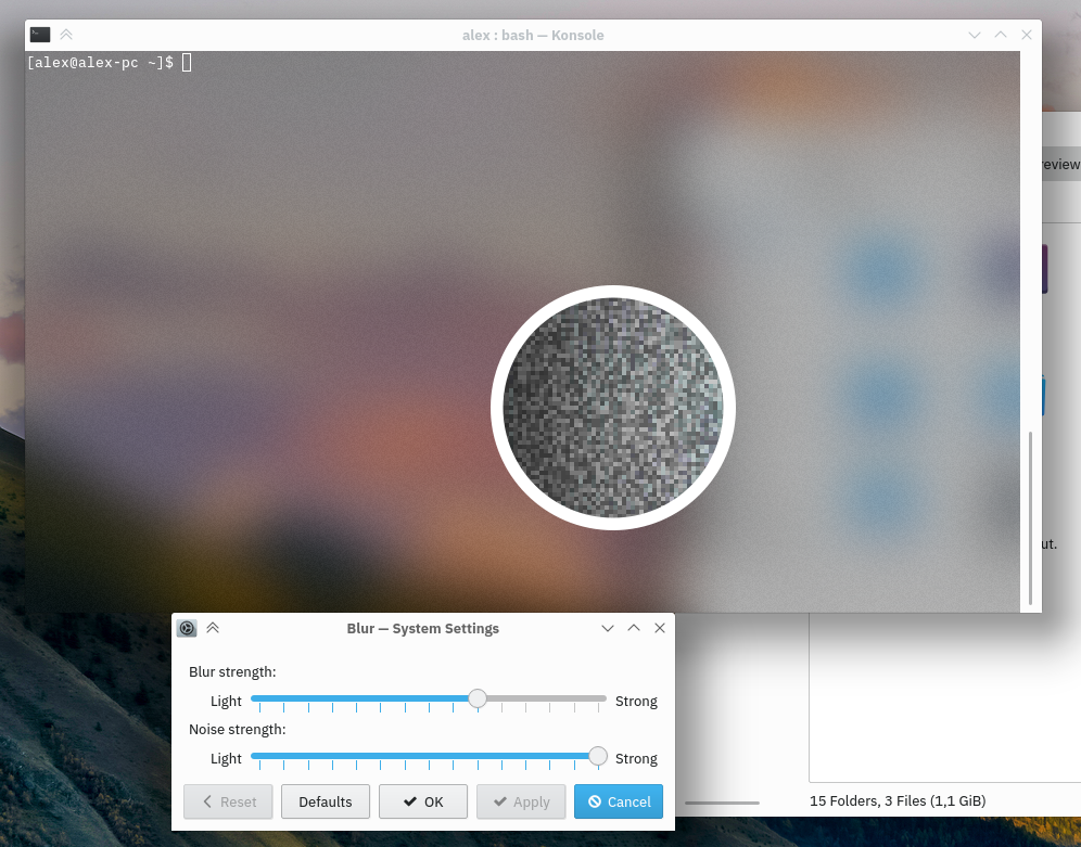
Zoomed and contrast boosted in circle
Microsoft Windows Acrylic #
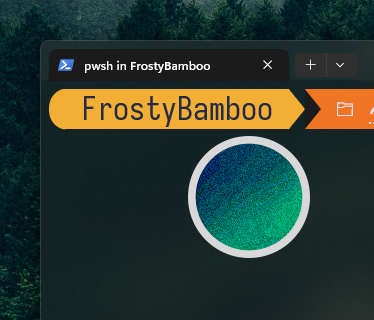
To finish off, here is how Windows 11 and its Acrylic does it. It applies both blur and noise to achieve the same.
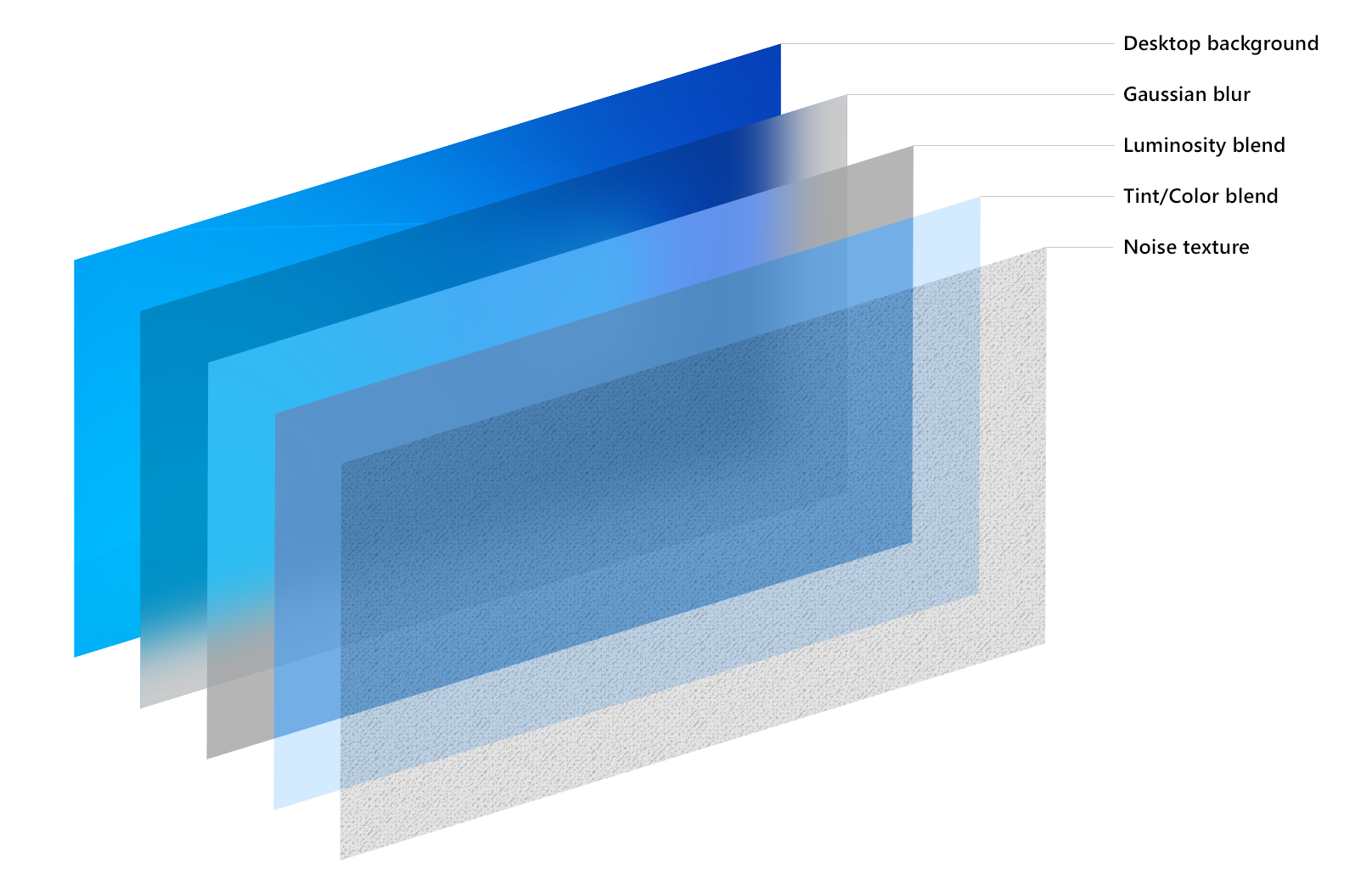
Here is how it looks in Microsoft’s “New Windows Terminal”. The circle has again brightness and contrast boosted to see the effect more clearly in the context of the article. Even though new Windows terminal is open source, the implementation of acrylic is within the source code of Windows itself, so we cannot take a look at the specific implementation.
And that warps up our little journey through all things color and hopefully none things banding.
Addendum #
Lobste.rs user luchs asked here for a way to determine the bit-depth of the current output, if one does not trust the software stack to do so correctly.
Do you have any good test images for determining a monitor’s color depth? Between applications, compositors, graphics drivers and monitors, it looks like a lot of things can go wrong. Monitors that accept 8 or 10 bit and then use dithering don’t help either.
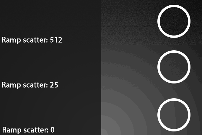
This is indeed an interesting test-case, so I quickly whipped up a 16-bit PNG of a dark, grayscale gradient, with no dithering. In terms of grayscale value, the gradient goes from 0-2 in 8-bit, 0-8 in 10-bit and 0-256 in 16-bit. The file is 1024px wide, so there is a new grayscale value every 4 pixels.

Here is how the test works. Load up the image, point a camera at it and take a photo with a long enough exposure to distinguish the color bands. The camera does not have to be anything special, an 8bpp jpeg is more than enough. You will need a dark environment though, since reflections on the dark screen will overpower the weak color differences. Depending on how many color bands you see, you can determine the true result of the bit-depth-ness hitting your hopefully better than 8-bit eyes.
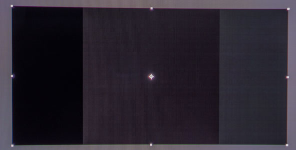
On an 8-bit monitor, you should see 3 distinct stripes. If the file is properly decoded with the sRGB gamma curve, then the stripes should be as per the photo above: first and last stripe exactly half the size of the middle one. (Due to the gradient starting and ending on integer boundaries and color bands forming in even sizes in-between)
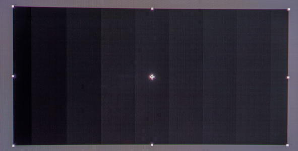
On a 10-bit monitor with proper software support, you should see 9 distinct stripes. All stripes should be the same size, except the first and last one, which should be half-sized. If you see 33, then your monitor and software are in 12-bit mode.
If the stripes are not even or you are seeing more or less than the numbers above, then something is going on in terms of color space during image decoding.
On Windows, Microsoft Edge skews the gradient to one side, whilst Firefox does not. It has either to do with Microsoft Edge applying extra color management or the brightness response curve being approximated as Gamma 2.2, instead of the piece-wise curve that it is, leading to a slight shift in how the 16-bit gradient is being displayed on the 8-bit output.
Your monitor’s color gamut and gamma settings should have zero effect on the number and distribution of stripes. Just the way of decoding the image should influences the result.